simulation environment
The simulation environment is coming along nicely. Images are used to represent environment characteristics at different vertical levels. The images are transparent to visualize the full environment. The environment supports the following.
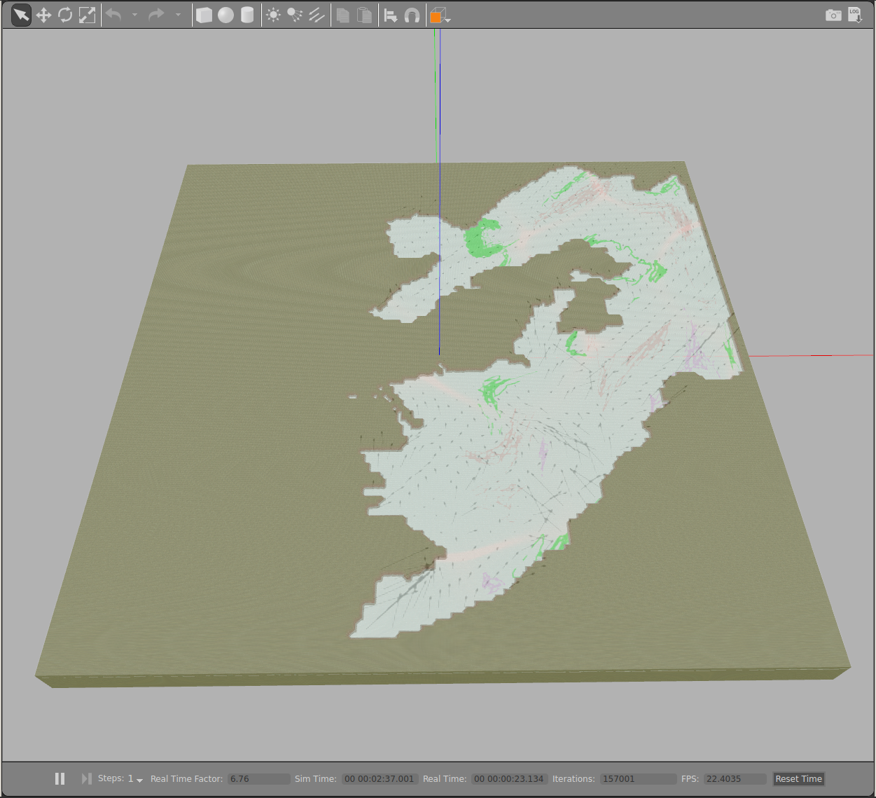
Target entities: Subsurface entities of interest. Each class of entity is represented by a pixel color value. These change at a an interval parameter. I just supply a directory of the images with an update rate.
Water currents: A vector field is overlaid on the environment to visualize the currents. At any given point in the water, objects can be affected by the currents. Any object can be affected by attaching the water currents plugin to the object’s model in the configuration file. The currents update at a parameter interval. The interval need not be the same as the target entities’.
Water surface: A transparent blue ground floor represents the water surface. The target entities are below this surface.
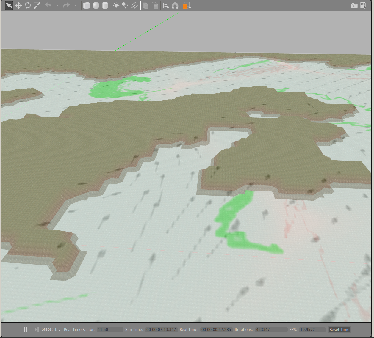
Terrain: A raster image of the region is used as a height map to generate 3D terrain. The robot can collide into the terrain if the path is infeasible.
Time: Working on getting the daylight to change. I have it adjust the ambient light at an interval to match times of day. It is a very simple system where noon is maximum light and midnight is minimum light. I expect this to be sufficient for initial experiments in mission planning. However, the light level does not actually change! I found that I need to make it a Visual plugin rather than a World plugin to be able to affect rendering during simulation. As it is, the time of day and light level is simply output at each interval in the terminal messages. Sufficient to find the solar energy available to the robot’s solar panels, but I want the entire simulation to be visual.
Video in which a robot is sent crashing toward shore by currents